Electronic Dice Game of 21 Using 555 Timer, CD4017, and 7447 With a Seven-Segment Display
by Ana Jeyakumar in Circuits > Arduino
95 Views, 1 Favorites, 0 Comments
Electronic Dice Game of 21 Using 555 Timer, CD4017, and 7447 With a Seven-Segment Display

Hello, my name is Ana Jeyakumar and this Instructable will walk you through my senior final project, a Electronic Dice Game of 21 built using a 555 Timer, CD4017 Decade Counter, 7447 BCD Decoder, and a Seven-Segment Display. The project might seem complicated at first glance, but I will walk you through a step-by-step process on how to build and code each portion, so don’t worry! But first, here is a simple explanation of how the project works.
At the start of the game, the player is welcomed by the serial monitor and prompted to roll a number by pressing the push button, which generates a random value from 1-6 on the seven-segment display. This value is then added to the score, with the objective being rolling until the player reaches a total of score of 21. If the player gets a score above or below 21, they lose. After each roll, the player can choose to roll again or stop playing by switching the slide switch OFF.The Electronic Dice Game of 21 uses a 555 Timer for clock pulses, CD4017 to randomize the dice value, a 7447 to show the value on the seven-segment display. The theory of how these components work together will be explained later!
After some preliminary research and discussions with teachers, I decided that I wanted to combine the Digital Circuits and Micro-Controller Units together, as I enjoyed these units the most. I made the Electronic Dice as a project in the beginning of the semester, and knew that through adding lines of code, I could turn it into a complex, fun game to play! Even though I struggled with building, wiring, and coding at first, this Instructable will show you how to easily make this project, even without prior knowledge in electronics. Let's get started, starting with the materials!
Supplies


For this project, you will require…
- 1x 555 Timer
- 1x CD4017 IC (Decade Counter)
- 1x 7447 Decoder
- 1x Push Button
- 1x Slide Switch
- 1x 10µF Capacitor
- 9x 1N4148 Diodes
- 1x 10kΩ Resistors
- 8x 1kΩ Resistors
- 1x Common Anode 7-Segment Display
- 1x Arduino UNO R3 (if required)
- 1x Breadboard (if required)
- 1x Wire Pack (if required)
Estimated project costs are above!
NOTE: some components are optional if you already have them!
Building Electronic Dice on Breadboard (Wiring 555 Timer)


NOTE: I HIGHLY recommend clicking the hyperlinked text which may have articles explaining components or chip pinouts if you are not familiar with them. I promise this will make the whole process easier!
Before wiring, you should plan the layout of your 21 Electronic Dice Game on your breadboard to ensure there is enough space for all components, as this project takes up the whole breadboard. Careful placement at the start will prevent the need to rewire later. Start by placing the 555 Timer on the far left side of the breadboard, followed by a push button, then the 4017 Decade Counter. Leave extra space before placing the 7447 decoder (space needed for diodes and resistors), and place the common-anode seven-segment display on the far right side (refer to the breadboard image above!).
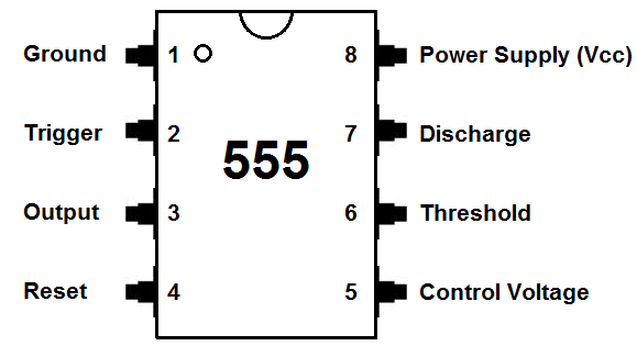
To make it simpler, we will separate the wiring into 3 steps for each integrated circuit, starting with the 555 timer. Here is a link for a 555 Timer Gate Pinout. Start by connecting the gate to power (PIN 8) and ground (PIN 1) ensuring the gate is placed with the groove on the left side to make wiring easier. Wire the reset pin (PIN 4) to power. Remember the 1kΩ resistors (PIN 7-6) are connected to power and a 10µF capacitor is connected to ground and trigger pin (PIN 2), and the output pin (PIN 3) is connected to a push button wired to ground with a 10kΩ resistor. My EasyEDA schematic file is included at the bottom, where you interact and closely look at connections. Take your time, and double-check that your wires and components are in the right pins.
How 555 Timer Works in 21 Game:
The 555 Timer is an integrated circuit that can generate precise time delays, pulses, or oscillations. It is commonly used in circuits like timers and basic clocks. In this project, the 555 Timer is continuously set in astable mode, which means it continuously produces fast clock pulse pulses (switches between high and low output states).
Wiring CD4017 Decade Counter


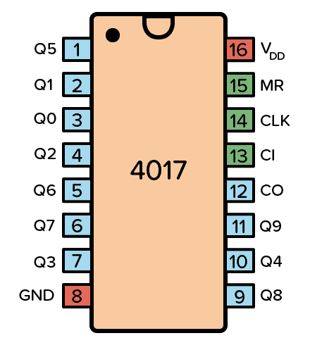
Next, we need to wire the CD4017 Decade Counter. Here is a link for a CD4017 IC Gate Pinout. Start by connecting the gate to power (PIN 16) and ground (PIN 1). Wire the clock enable pin (PIN 13) to ground. Additionally, connect the push button from the last step to the clock input pin (PIN 14). Follow the chip with 9 1N4148 diodes, and connect the remaining output pins by referring to the schematics and images above, which are labeled clearly.
NOTE: Be extra careful with diode connections. Since the diodes are so close together, a common mistake is wiring in the wrong pins. Be careful and wire one output to a diode at a time.
Following the 9 diodes, connect 4 1kΩ resistors to ground. Some diodes are connected to these resistors. Here are the connections;
Diode 1 is connected to R4
Diode 2 is connected to R5
Diode 7 is connected to R6
How 4017 Works in 21 Game:
Clock pulses are sent to the CD4017 Decade Counter, which is also an integrated circuit that counts clock pulses and activates one of 10 output pins one at a time (Q0 - Q9). In this game, only 6 outputs are used to represent dice values 1-6 (Q0 to Q5), and a seventh output (Q6) is connected to the reset pin so the count loops back to 1 (similar to a real dice). When the button is pressed, the clock runs extremely fast (so numbers are hard to see), and when the button is released, the clock stops and produces a random, unbiased number.
Wiring 7447 BCD Decoder


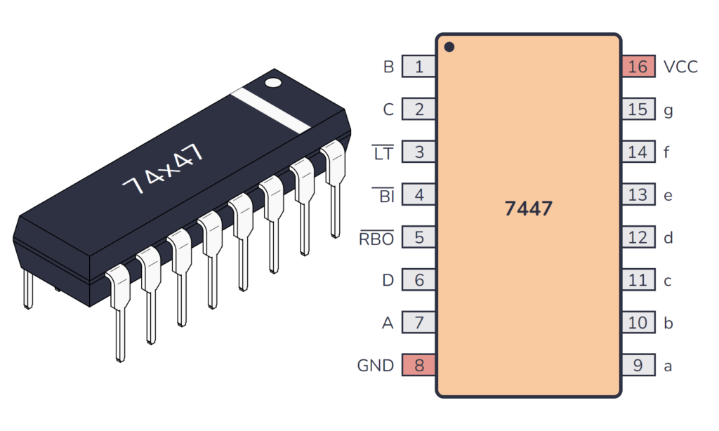
Lastly, we need to wire the 7447 BCD Decoder. Here is a link for a 7447 Gate Pinout. Start by connecting the gate to power (PIN 16) and ground (PIN 8). Wire (PINS 5, 4, 3) to power. This chip is connected to the 4 1kΩ resistors we placed in the last step. Here are the connections;
R4 is connected to (PIN 7)
R5 is connected to (PIN 1)
R6 is connected to (PIN 2)
R7 is connected to (PIN 6).
Additionally, the 7447 decoder is connected to the Seven-Segment Display. Since this part can be confusing, I’ve included a hand-drawn schematic of connecting the 7447 to the seven segment display above. Here are the connections;
Segment a = PIN 13
Segment b = PIN 12
Segment c = PIN 11
Segment d = PIN 10
Segment e = PIN 9
Segment f = PIN 15
Segment g = PIN 14
How 7447 Works in 21 Game:
The outputs from the 4017 are converted into binary numbers (a way of representing numbers using only two digits: 0 and 1) using diodes and pull-down resistors, then sent to the 7447 BCD to 7-Segment Decoder. This integrated circuit translates these binary values into the correct pattern to display on the Common Anode Seven-Segment Display ( a number from 0-6).
This is how the electronic dice works and wired! Don’t worry, you have done the most complicated part of the process! Now let’s move on to the code!
NOTE: It is CRITICAL that the electronic dice on the breadboard works as intended. If it doesn't work at first, don’t worry. Go back and check that your connections are in the right spot, as even a tiny mistake can make the circuit not function.
DO NOT START THE CODE UNLESS THIS IS DONE!
Coding (Variables)

.jpeg)

Now, we are going to use this circuit to code the game!
NOTE: The code file is included at the bottom on this section
To start with the code, we declare variables for the different Arduino pins, which helps the Arduino remember important information and game data. The general format looks like this;
int (variable name) = pinumber;
**remember to add the semicolon at the end!
In this game, the variables (in6 - in1) represent the six output pins of the CD4017 that correspond to dice values 1 through 6. These pins are connected to the Arduino so it can read which number was rolled. Here are the connections to the arduino pins below:
The variables (in6 - in1) represent the six output pins of the CD4017 that correspond to dice values 1 through 6. These pins are connected to the Arduino so it can read which number was rolled. Here are the connections to the arduino pins below:
int in1 = 2;
int in2 = 3;
int in3 = 4;
int in4 = 5;
int in5 = 6;
int in6 = 7;
The (rolled) variable is used as a flag to detect when the dice is rolled and the (score) variable is responsible for keeping track of the total score as the player rolls multiple times. The (currentState) and (prevState) variables store the current and previous state of the push button, allowing the Arduino to detect a button press and ensure the code runs only once per press. These variables are initialized to 0, because 0 represents LOW state (gives Arduino a starting point for detecting first button press).
The (button) variable is used to detect when a button is pressed, while the (slide) variable tells the Arduino to stop or continue running the game. Here are the connections to the arduino pins below:
int button = 8;
int slide = 9;
Downloads
Coding (Setup Function)


Now that you've initialized all of your variables, you must set them to input or output in order to connect the pin in void setup(), which is a function that runs once when the Arduino starts. This section of the code tells the Arduino which pins are being used and what their functions are; either sending signals (OUTPUT) or reading signals (INPUT).
Inside void setup(), all the pins are configured using pinMode();. Since the Arduino will be reading signals from the electronic dice to start the game, all of the variables are set using this format:
pinMode(variable name,INPUT);
The button, slide switch, and six 4017 output pins are set as INPUTS (as the Arduino reads these signals from the dice), so they are set like this;
pinMode(button,INPUT);
pinMode(slide,INPUT);
pinMode(in1,INPUT);
pinMode(in2,INPUT);
pinMode(in3,INPUT);
pinMode(in4,INPUT);
pinMode(in5,INPUT);
pinMode(in6,INPUT);
Lastly, in order to guide the user on how to play the Game of 21, we are going to use the Serial Monitor (tool in Arduino IDE that displays text sent from Arduino). To do this, we need to add a few pieces of code;
Serial.begin(9600);
Serial.print("Welcome to the Game 21! Let's Play!");
This starts serial communication and displays a welcome message on the Serial Monitor. So far, we have told the player that the Game of 21 has started.
Coding (Loop Function)


Next is the loop function, which is where the main game logic happens. This function runs continuously and controls how the game works.
Detecting Button Press:
The first line of code checks if the slide switch is ON or OFF. If the slide switch is set to the LEFT, it is ON (HIGH) and the game is active. If the slide switch is set to the RIGHT, it is OFF (LOW) and the game ends.
If the game is active (slide switch ON), the Arduino reads the button state. By comparing currentState and prevState (current and previous state of button), the code detects a new button press. This function is extremely important because it prevents multiple rolls from being counted when the button is held down!
If a new press is deleted, then rolled is set to 1, and if no press is detected, it is rolled is set to 0
Starting Game:
When rolled is true (set to 1), the Arduino waits for 1 second before reading dice value (which gives signal time to stabilize). This delay is extremely important because without it, the game would register multiple rolls from a single button press, which would cause the score to increase incorrectly!
The Arduino then reads which 4017 output pin is HIGH, to determine the dice number (1-6). Whichever pin is read as HIGH, that value corresponds to the rolled number and added to the score. After the first roll, the updated score is displayed on the serial monitor, and the player is prompted to “roll again” to reach the number 21.
For example, in the image above, I roll and get the number 4. This means the signal is HIGH on Arduino pin 4 (in3). The Arduino detects this HIGH signal and adds 4 to the score variable. This score is then displayed on the serial monitor.
Then, I roll the number 6. This means the signal is HIGH on Arduino pin 2 (in1). The Arduino detects this HIGH signal and adds 6 to the existing score. In this case, since 4+6 =10, a new score of 10 is displayed on the serial monitor.
Ending Game:
The final lines of code are for when the player chooses to end the game. If the player has reached 21, or has gone below or over 21, they can end the game by setting the slide switch as OFF. Then, a “Thanks for Playing!” A message is displayed on the serial monitor along with a final score.
For example, in the image above, I ended the game after surpassing 21, resulting in a final score of 23. The serial monitor displays a thank you message and shows the final score.
Video Demonstration
Once you've finished the code, you're done! Congrats on building the project! Attached is a video link which shows the demonstration.
Link for Project Demonstration